 Guide
Guide Mounting and Integrating a Motor Drive
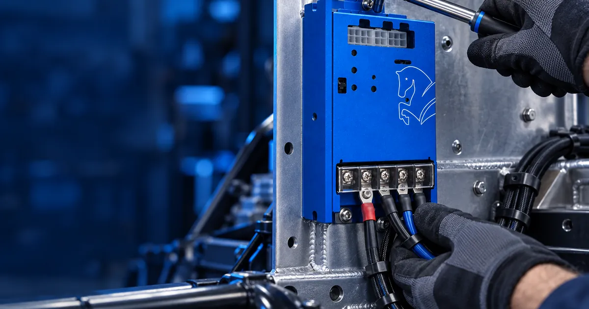
Choosing the right drive is half the job; the other half is connecting it properly. A significant share of the problems seen in the field come not from the board itself but from mounting and wiring. This article walks through integration in order.
1. Placement
- Mount the drive in full contact with a metal surface at a rigid point; the housing is also a heatsink.
- Leave air circulation around it; do not wrap it in the cable loom.
- Pick a location accessible enough to unplug connectors; serviceability should be planned from day one.
- Keep it away from areas exposed to water and mud spray.
2. Power Wiring
Battery and motor cables should be short, thick and properly torqued. A loose power terminal heats up, its resistance rises as it heats, and that loop leads to melting fairly quickly. Tighten terminal screws to the value given in the manual and re-check once after the first hours of operation. Route power cables separately from signal and communication cables.
3. Feedback Connection
Brushless drives must know the rotor position. The shield of Hall, encoder or resolver cables should be grounded at one end only and must not run parallel to power cables over long distances. An incorrect phase-to-Hall order shows up as the motor juddering or not turning at all; that is a sequencing error, not a fault.
4. Communication
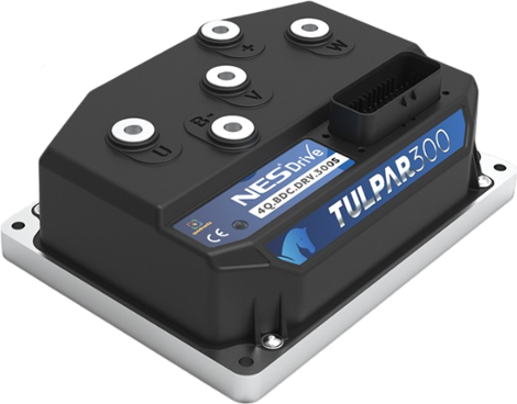
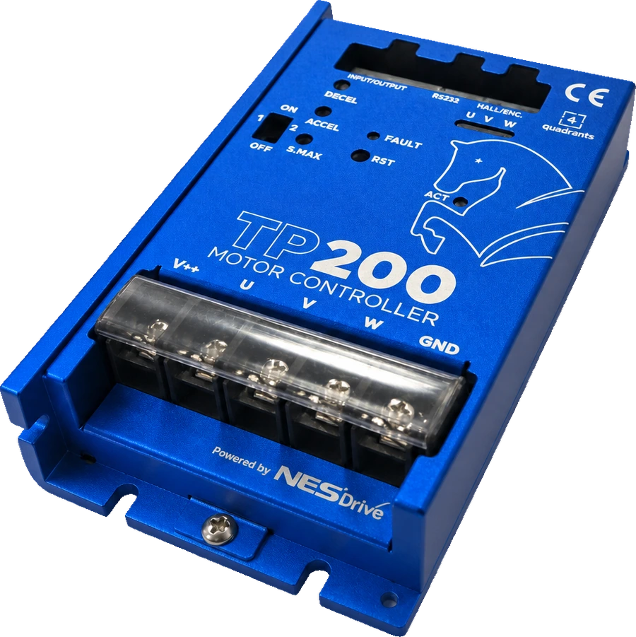
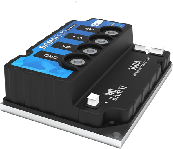
The whole TULPAR series plus BAMSI 300 and 250 communicate via Modbus (BAMSI 200 uses USB TTL); CANopen is available on TULPAR 100, 150, 250, 275 and 300. A CAN bus needs a termination resistor at each end; with termination at one end or none, the bus runs unreliably. Address and baud rate must match the host controller (PLC or vehicle computer) exactly. You can see which protocol each model offers in the specification table on its product page.
5. First Power-up
- Jack the vehicle up or lift the wheels off the ground; the first direction test is not done under load.
- Connect with NESDrive Studio and enter motor parameters and current limits.
- Verify direction of rotation and feedback readings at low speed.
- Test braking and regenerative behaviour unloaded, then move to load gradually.
- Watch the temperature during the first hours; heating faster than expected points to a mounting or cable cross-section problem.
Share your application requirements and our engineering team will recommend the best NESDrive model.
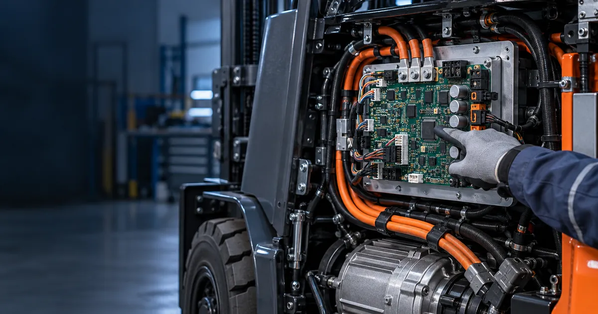 Guide
GuideWhat Is a Motor Controller? The Brain of an EV
What does a motor controller do? The role of the “brain” in electric forklifts, pallet trucks and battery vehicles, its types and how to choose one.
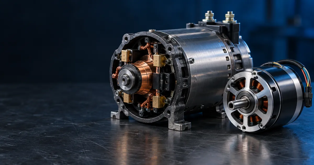 Guide
GuideBLDC or Brushed DC? How to Choose the Right Motor Drive
The difference between brushed DC and brushless (BLDC) motor drives, which one to pick for your application, and 5 key criteria when selecting a drive.